|

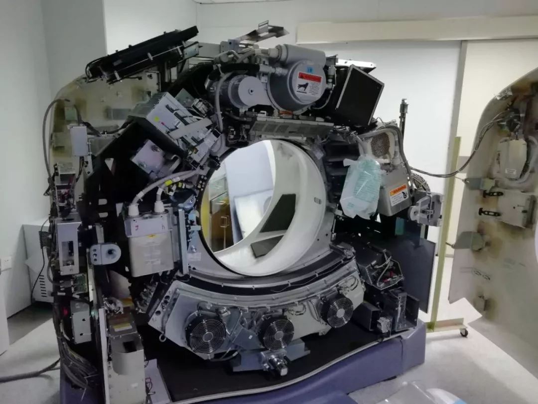
一.故障现象:球馆小焦点灯丝断 二 球馆更换步骤具体如下:和普通lightspeed 16 和brightspeed16 安装步骤基本差不多。 1.安装前准备工作,需要工具,扭力扳手,套筒,14的扳手,葫芦(百分表),及其他常用工具。 2拆开两个侧盖,取下上面的两个盖板.(注意右侧有个压合维修开关记的要压) 3. 将侧面的120V和HV and axial drive后面的两个开关分别打至OFF位 4.拆掉前盖,注意Gantry和前盖的连线 5. 将SYS打至OFF位,Service打至ON,手动旋转球管到90度的位置,栓上固定销子 6. 检查开关全部打至OFF位,然后关机,最后关掉稳压器 7. 松开管球上的插头和电缆头,用塑料纸将电缆头包好并固定好 8.松开Gantry右上方的轨道螺丝,拉出轨道并安装上吊葫芦 9.用吊葫芦挂住管球并使其链子绷紧,检查所有的干扰物已经处理好并且确认. 10.按要求拆下球管,注意卸螺丝事项:一般的话先把最下面的两颗先松了,再松上面的. 11.按要求装上球管,把球管转到0度位置调整螺丝的松紧情况,开始的时候一般不要上的很紧,以便方便后面的调整. 12.把百分表装到指定的位置,检查一切准备工作已经做好 14.清灯丝,填写球馆信息 Filament data。Diagnostics-------generator test -------clear filament Aging / tube stats. 特殊软件版本在generator tools里面 15.做机架balance 16开始做BOW .ISO(在做此步骤时,可能会提示温度过高,这个时候不要慌,一般等上40分钟后温度降至:400度以下就可以做了)(一般情况下就是最开始就做BOW ,ISO两个就不会提示温度过高了) 输入球馆当前位置0degree,点ok,如下图a b c,然后dismiss,点击第二scan,最后计算 做完bow ,开始做iso,先扫空气,然后用机头支架插个内六打点,用激光定位灯的内线打点距离2cm,调位置时,up逆时针,down顺时针,每次调的时候 都要把螺丝稍微柠孙,然后再调,在拧紧。百分表(未尝试过),调试过程要有耐心。一直到提示iso pass 做全校准,为了防止有为影,80 100 120 140,都得做,做小模时不可以扫到铁。顺序是 先空气,中大小,每个过程必须在10分钟内调试完,否则就得重新来。调试过程床高度通常在142-145之间,这样剩下的就是微调机头支架。 中莫校准 CT值校准
Old Tube RemovalSlide out the gantry rear cover, and rotate the top fan assembly outward.Remove and set aside gantry side, top and front covers. Illustration 1: Top Fan Assembly
(For CT System Only) Remove the M10 screws holding support bracket for the right front gantry cover and set the assembly aside. It may be necessary to tilt the gantry back to remove the third bolt if present which is not normally installed on some systems. (For  ET Systems Only with the BrightSpeed Gantry) There may or may not be a lower screw present. If the lower screw is present it must be permanently loosened and left loose using the short stubby 8 mm hex wrench provided with FMI 13693. The wrench is located in the Service Cabinet on site. If necessary this wrench (P/N 5367896) can also be ordered and should be left on site. ET Systems Only with the BrightSpeed Gantry) There may or may not be a lower screw present. If the lower screw is present it must be permanently loosened and left loose using the short stubby 8 mm hex wrench provided with FMI 13693. The wrench is located in the Service Cabinet on site. If necessary this wrench (P/N 5367896) can also be ordered and should be left on site. Illustration 2: Right Front Gantry Cover Support Bracket
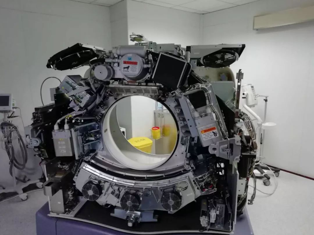
Turn off the AXIAL DRIVE ENABLE, HVDC ENABLE, and 120VAC switches. Turn off facility power to PDU and lockout/tagout according to lockout/tagout procedure. Rotate the Gantry until the x-ray tube reaches the 3 o’clock position.
Illustration 3: Tube Angle to Loosen and Torque M12 Screws
Engage gantry rotational lock, and check that the gantry is securely locked by attempting to rotate the gantry by hand. Insert the lifting post, boom and chain hoist. Reference Illustration 2. Disconnect the Smart I.D. system cable, from the Smart I.D.
Disconnect the 4 pin mate-n-lock pump and fan power system cable.
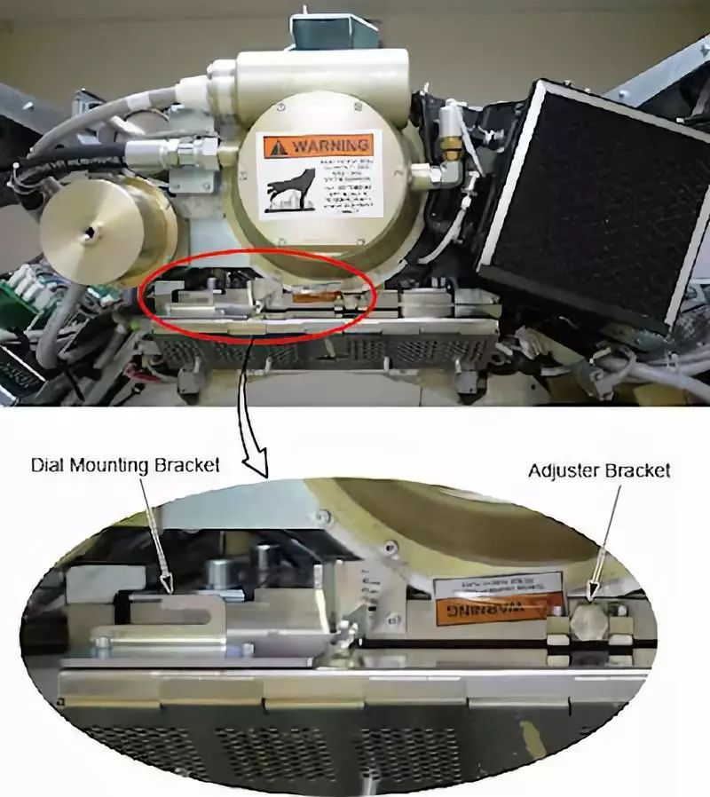
Disconnect the thermal sensor cable. Remove the anode and the cathode cable: Illustration 5: Dial Mounting Bracket and Adjuster Bracket
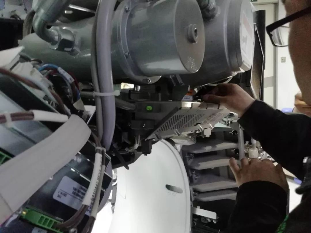
Loosen each cable’s locking ring with the spanner wrench. Pull each cable terminal out of its receptacle. Ground the end of the cables to the Gantry frame. Wipe up any oil that drips from the cable terminal. Use paper towels to soak up any oil in the wells. Remove the dial mounting bracket Remove the z-align adjuster bracket
The x-ray tube is attached to the Collimator with a Tube Mount Bracket Assembly. Remove the mounting plate & x-ray tube from the Collimator by removing the four M12 cap screws and lock washers, and two washer plates, with a hex socket driver. With your hand, reach behind the radiator to the screws from either side of the Xx-ray tube center section while removing the bolts with two 12-inch extensions (24 inch length) on a ratchet. Throw these M12 bolts and washers away, as they should not be reused.
Illustration 6: X-Ray Tube Mounting
Throw these M12 bolts and washers away, as they should not be reused. Slide the x-ray tube forward and remove it. Remove the washer plate Remove M12 cap screws.
Carefully swing the tube clear of the gantry.
Inspect the Bowtie Filter (refer to Inspect Collimator Filters). It is possible that the Bowtie Filter is contaminated and the Primary Copper Filter is not contaminated.
Verify that the Lexan plastic has been removed from the collimator. If it is still there, remove it following the procedures in Lexan Removal .
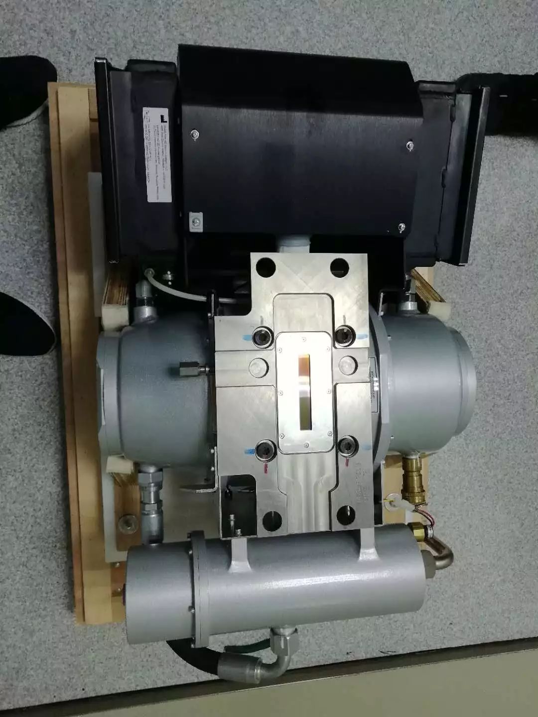
3.2 New Tube Installation
Allow the tube unit to warm to room temperature before you install it.
Re-check facility power and make sure it is off.
Use the hoist to lift the new tube unit:
Z-Align Adjuster Bracket Dial Mounting Bracket
To ease installation, fasten the top pressure plate to the rotating structure first. Then attach the bottom pressure plate. Use new bolts and washers from tube crate. Make sure to select the proper bolts. There are instructions in the crate, and on the tube itself.
Install the following brackets: Set final torque to: | 49 ft.-lbs | 66 N-m | 590 in-lbs | 680 kg-cm |
Fasten the lower and upper and pressure plates to the rotating structure with the four M12 (50 mm) bolts, and set pre-load torque to: | 25 ft.-lbs | 33 N-m | 295 in-lbs | 340 kg-cm |
Install the washer plate.
Position the tube on the gantry: The “crosses” on the mounting plate and on the collimator should fit in perfectly when the tube is aligned properly
Connect the Smart ID to the tube smart ID board.
Connect the tube pump and fan power cable to the 4 pin mate-N-Lock connector.
Connect the thermal sensor cable.
Remove the plastic cap plug from each cable receptacle on the tube unit. | NOTE: | Take care not to lose the rubber quad rings for the High Voltage cables. |
Lightly wet the new rubber quad ring with transformer oil.
Return the quad ring to its slot at the top of the receptacle retaining ring. Pour transformer oil into the receptacle to a depth of 10 mm (0.375 in). Be sure to route the HV cable as shown in Illustration 7. Illustration 7: HV Cables Properly Routed and Secured
Align the cable terminal orienting key with the notch in the receptacle. Slowly insert the cable, to engage the connector pins, and seat the cable in the well. Carefully wipe up all excess oil. Secure HV Cables using large tie-wraps, as shown in Illustration 7.
Disconnect hoist from tube and boom.
Remove the post and boom from the gantry. Reference Illustration 2. Check for oil leaks: Wrap rags or paper towels around the cable horns, and tape them into place. Manually rotate the tube to the 6 o’clock position. Return the tube to the 3 o’clock position Remove the toweling and wipe up all excess oil. Wipe off the cable horns, locking rings and strain reliefs with an alcohol-dampened rag. Repeat with a dry rag. Wrap the cable strain reliefs and locking rings with a single layer of absorbent paper tissue. You can use two inch wide strips cut from a paper napkin. Wrap the bottom edge of the paper around the top end of the cable horn, and tape it in place. Extend the top edge of the paper over the top of the locking ring, and tape it to the plastic cable strain relief. Remove paper after leak check.
If oils leaks are found, tighten the locking ring slowly until there is no leakage, paying attention to not over tighten. Install the right gantry front cover bracket. Reference Illustration 2. | NOTE: | For PET systems only reinstall the top M10 screw. If the lower screw is present on a PET system do not tighten it. leave the lower screw loose. |
Restore system power at the main disconnect panel. Turn on gantry 120 VAC, HVDC ENABLE and AXIAL DRIVE ENABLE on the service switch panel. Wait at least 10 minutes to warm up the filament. Press [ESTOP RESET] on Service Switch Panel and wait until scan hardware is reset.
3.3 Stepup, Checks, Alignments and CalibrationsChecklist Tie-wraps and cables are in place. Proper torque specifications are followed for all fasteners (see Torque Wrench Information). New mounting bolts and washers are used for mounting the tube; old mounting bolts and washers are discarded.
- Fast Calibration Detailed Calibration Collimator Calibration Install the gantry right side cover. Press [ESTOP RESET] on the Service Switch panel, and wait until scan hardware is reset. Turn ON [HVDC ENABLE], [AXIAL DRIVE ENABLE] and [120VAC] switches on the Service Switch panel. Install the gantry front cover, rear cover, top cover, left side cover and scan window. Turn OFF [HVDC ENABLE], [AXIAL DRIVE ENABLE] and [120VAC] switches on the Service Switch panel. Hot ISO Alignment HHS Scans (Advanced) Filament Calibration High Voltage Tank Feedback Resistor Verification Meter Verification Gantry Balance Procedure Tube Alignment (Restricted) Cold ISO Alignment Z-Alignment Gantry Rotation Safety Check Reset TnT (Only select Tube TnT Data) Tube Install Certification
4 FinalizationSystem Scanning Test
Quality Assurance Test
New Tube Configure
Save Generator Runtime Parameters (See Save Restore Generator Runtime Parameters)
Save System State
Prepare tube crate for returning old tube. | NOTE: | Use provided labels to identify old tube as good or defective. |
| NOTE: | If tube is being restocked as good, re-band cardboard to crate using strapping instructions provided in crate. |

| 


 发表于 2020-9-17 09:46:48